Resistors
Resistors are a very important part of any electrical device there is , so you have to be able to identify and test a resistor and know how they affect a electric circuit .
A resistor limits the amout of current that is passed through it when it is wired in a circuit, to protect an electric component . Resistors reduce power with resistance, witch is measured in ohms . There are many different sizes of resistors that will only let a cirtain amout of current through and if you were to give the resistor more power than it can handle, the resistor will short out or will fail and burn out the component you were trying to save in the first place, so it is very important that you use the right one for the job!
Above: here is a chart that i have uploaded from the internet from this website :(
http://www.elexp.com/t_resist.htm)
Bellow: Is another helpful chart, that helps you figure out how many ohms any resistor may be. Witch i have also uploaded from the the internet (http://www.led-depot.co.uk/Diagrams-and-Dimensions/Diagrams-Dimensions)
In practical we had to pick out 6 random resistors and calculate and measure these resistors and see if they were in good operating order.
To work resistance you will need to use the colour charts above.
Example: Red, Red, Red, Gold= 2200 then you have to +/- 5% which is 2090 to 2310 ohms
when I measured this resistor with my multimeter on the resistor function it read 2.182 K ohms.
When you have resistors wired in series you have to add both of the resistors together to get the total between the two, because the power has to travel throught both separately.
when you calculate resistance in parallel you have to mutliply both of the resistances, then add both of the resistances and then you divide the two equations and then you will have the resistance in your parallel circuit.
e.g. 1 X 2 = 2
------------
1 + 2 = 3
PR= 0.666ohms
Diodes
http://www.gadgetjq.com/tach_install.htm
http://www.mpoweruk.com/semiconductors.htm
Diodes are designed to stop revers spikes of power, for e.g. electrical one way valves. Diodes are made up of positive and negative material and have p-n junction . When power is traveling through a diode there is a volt drop of aporxoitely of 0.6v to 0.7v and this is because there has to at lest this mutch voltage to operate, because the voltage has to jump over the p-n junction which is sometime refurd to as the knee voltage.
In a diode the are even amounts of positive matter (holes) as there are of negative matter (electrons) and when the voltage gets over 0.6volts the electrons strat moving to the holes on the p-matter creating a hole in the n-matter and so positve is atracted to negative . But when in reverse bias the positive and negative repel against each other which causes the p-n junction to become larger, this will make the gap/junction bigger making it much harder for the electrons to cross.
We had to complete in practical a task to find the volt drop of a diode and LED in forward and reverse bias using a multimeter in the diode test function.
| Voltage drop in forward biased direction | Voltage drop in reverse biased direction |
| LED | 1.8V | 0V |
| Diode | 0.7V | 0V |
How you can identify the anode cathode without a multimeter
LED - the longer leg is the anode and the shorter leg is cathode
Diode - the cathode leg will be the one closest to the stripe. The anode will be the other one aow.
Calculate the current flowing through the diode.
Calculated: I=(Vs-Vd)/R
(5-0.7)/1000=0.0043A~4.3mA
Measured:
4.7mA
The measured reading was abit greater than calculated, this could be due to a bad connection or the power source might not be on 5V and the diode is good.
Calculate the voltage drop across the diode:
Calculated: Vd=Vs-(IXR)
5V-(1000X4.3)=0.7Vd
Measured: 0.64Vd
I have replaced the diode with a LED, calculated and measured the current:
Calculated: I=(Vs-Vd)/R
(5-1.8)/1000=3.2mA
Measured: 3.51mA
The LED has a higher Vd and lower current than the diode because the led has a higher knee voltage and needs at least 1.8v to operate and the diode only needs 0.7v
Experiment 3:
What is the value of Vz?
Vz=5V
Vary voltage supply from 10V~15V
10Vs=4.26Vz
12Vs=4.5Vz
15Vs=4.67Vz
The higher th voltage the more voltage is being bypassed through the zener diode to save the RL
This circuit could be used for a clock radio.
Reverse the polarity of the zener diode.
What is the value of Vz?
The Vz=0.76Vd, that is because the zener is in forward bias and operates as a normal diode and the reading is knee voltage.
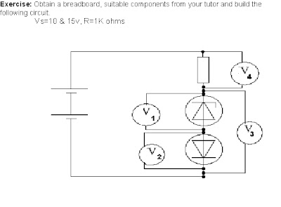
Experiment 4:
| 10V | 15V |
| Volt drop V1 | 4.64V | 4.8V |
| Volt drop V2 | 0.64V | 0.67V |
| Volt drop V3 | 5.28V | 5.48V |
| Volt drop V4 | 4.91V | 9.69V |
| Calculated current A | 4.72mA | 10.52mA |
The uses 5V to operate in reverse bias and in forward bias it uses 0.6~0.7V and in the closed circuit the resistor is the only component left to use the rest of the voltage supply which is kirchoffs law.
Experiment 5: The capacitor
| Circuit number | Capacitance (uF) | Resistance (Kohms) | Calculated time (ms) | Observed time (ms) |
| 1 | 100 | 1 | 0.5s | 600ms |
| 2 | 100 | 0.1 | 0.05s | 70ms |
| 3 | 100 | 0.47 | 0.235s | 320ms |
| 4 | 330 | 1 | 1.65s | 2s |
To calculate the time the formula is RXCX5=T
1. 1000X100uFX5=0.5
2. 100X100uFX5=0.05
3. 470X100uFX5=0.235
4. 1000X330uFX5=1.65
1
2
3
4
The larger the resistance, the longer it will take the capacitor to charge.
The larger the capacitor the slower/longer it will take to charge.
Experiment 6: BJT
| Transistor number | Vbe | Veb | Vbc | Vcb | Vce | Vec |
| NPN 547 | 0.722 | OL | 0.717 | OL | OL | OL |
| PNP 557 | OL | 0.722 | OL | 0.718 | OL | OL |
Experiment 7:
Connect the multimeter between the base and the emmitter and note the voltage reading and explain what the reading is indicating.
0.789V This reading is indicating that the volt drop Vbe is normal.
Connect the multimeter between the collector and emmiter:
55.4mV. This is because the transistor is in the saturated region.
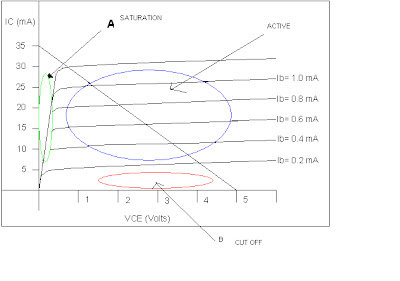
A= staturation region and that is when the transistor is fully open and current can flow freely and has little resistance and less heat is created .
B= cut off region and is when the transistor is turned off and this is because there is not enough current for the transistor to turn on.
When the transistor is operating in the active region there is quite abit of resistance and there for heat is generated and is not ideal.
The power dissipation at the graff shows at vce 3volt the IC=14ma and IB=0.5ma
Calculations of beta at Vce 2,3&4 volts is,IC/IB=B
2. 21/0.15=28b
3. 14/0.5=28b
4. 7/0.2=35b
Experiment 8
In this experiment i have measured voltage and current for vce, vbe,ic and ib.
I have used a bread board and 470r for rc and a bc547 npn transistor and i have picked out 5 different resistors for the rb which very from 2k2 to 1m .

| Rb | Vbe | Vce | Ib | Ic |
| 1 | 4k | 0.766v | 32.3mv | 2ma | 7ma |
| 2 | 4k7 | 0.76v | 34.1mv | 0.92ma | 6.36ma |
| 3 | 7k | 0.75v | 39.4mv | 0.62ma | 6.35ma |
| 4 | 10k | 0.738v | 46.4mv | 0.43ma | 6.33ma |
| 5 | 1M | 0.64v | 2.531v | 0.4ma | 1.36ma |
When the resistor gets larger the vce readings has a larger volt drop and this because the transistor is getting thurther away from being in the saturated region and the transistor is not hard switching.
On the vbe, the higher the resistance the lower the volt drop is .
On the ib current, the higher the resistance got the less amps are able the travel through the ib.
On the ic side the same thing is happerning as the ib side of the circuit and this is because the resistance at rb is controling how much the transistor is opening, limitering how much current can go through the transistor.


